|
|
Post by 0141trainmad on Jul 26, 2010 20:57:49 GMT
hi i am a new member and need some help
i downloaded the sheets but there does not appear to be a list of components
my electronic knowledge is limited although i have built speed contollers for model boats and model railways in the past.
can anyone help ?
i have started building a railway again after a forty year gap and have been fitting bachman decoe6.rs to locos purchased from ebay but as i still have some 18 locos to fit decoders to the costs are getting out of hand
regards robin dow
|
|
|
|
Post by Paul Harman on Jul 28, 2010 17:14:28 GMT
Robin
The component values are in the function decoder zip file. The circuit of the motor decoder and function decoder are identical apart from the motor drive amplifier which is an L272M op amp.
I have on my 'to do' list a little project to make a couple of updates to the motor decoder download package now that the kits are available from the sales dept. I will include a component list.
|
|
|
|
Post by kennedylanduk on Sept 21, 2010 17:34:14 GMT
Component list (for myself as well, I intend to start building some of these).
IC1 : PIC12F629
IC2 : L272M
IC3 : 78L05 regulator
D1 : 1N4148
D2 : 1N4148
D3 : 27V zener diode
D4 : UF4001 {I think}
D5 : UF4001 {I think}
D6 : UF4001 {I think}
D7 : UF4001 {I think}
C1 : 1uF 35V radial tantalum electrolytic
C2 : 100nF axial multilayer ceramic
C3 : 470nF radial multilayer ceramic
C4 : 100nF axial multilayer ceramic
R1 : 10K 1%
R2 : 10K 1%
R3 : 2K2 1%
R4 : 2K2 1%
R5 : 4K7 1%
R14 : 10K
R15 : 47R 2W
|
|
|
|
Post by kennedylanduk on Sept 21, 2010 17:35:52 GMT
Will any op amp do for this? Only asking as I've got a few left over from audio projects over the years.
|
|
|
|
Post by Paul Harman on Sept 21, 2010 21:51:07 GMT
No! You need a dual power op-amp with enough power to drive a motor - which the L272 can do.
The 2K2 resistors (R3 and R4) can be replaced with 1K 1% types which may provide better decoding at higher track voltages without compromising performance.
|
|
|
|
Post by Gareth on Dec 27, 2010 7:25:09 GMT
Hi
I would like to run a number of old Tri-ang motors with this decoder but I am concerned that the running current of the motors (± 700ma) is close to the max of the L272. Is there any way that a "booster" stage can be added to allow for say 1.5A running. These old Tri-Ang locos have plenty of room and can take a second board if neccessary.
|
|
|
|
Post by Paul Harman on Dec 27, 2010 15:02:13 GMT
If you are a bit worried you can just use a pair of L272 in parallel which will double the current that can be supplied by the L272 and beef up the diodes to UF5401 or similar.
I don't think that you need to worry though. The L272 is thermaly protected as well as being protected against over current at 1.6A. I also suspect that 700mA is not likely to be sustained continuously in normal use. I would recomend that you try it as is, perhaps make provision to add the extra L272 later if the loco is seen to slow after a bit of running.
There is value in adding an extra L272 if you have more than one motor in the loco (twin power bogie diesels for instance) where each motor can have it's own L272.
|
|
|
|
Post by Gareth on Dec 28, 2010 12:08:25 GMT
Hi Paul
My local RS store have the L272 s in stock and I hope to get those tomorrow. However the UF5401's are on back order but they have the UF5406 in stock. Will they be OK?
Gareth
|
|
|
|
Post by Paul Harman on Dec 28, 2010 12:53:26 GMT
The UF5406 should be fine.
|
|
|
|
Post by Gareth on Dec 28, 2010 15:14:45 GMT
Hi Paul
I have just realised that my posting was almost the same as a previous posting re Component Change.
Appologies.
Gareth
|
|
|
|
Post by martinp on Jul 28, 2014 19:33:46 GMT
Paul, Ordered my motor decoder kit and received extremely promptly - thank you  ) However; I built the kit up today, testing as I went and all was well. Without the decoder attached to the loco, but supplied with track power from my Massoth 1200Z central station, I could control the voltage levels between pins 1 & 3 of the L272 chip fine. Seeing the polarity reverse as expected with direction change on the Navigator. This all seemed as I expected. When I connected to the loco motor, placed the loco on track and advanced the throttle on the Navigator, the loco moved a couple of inches and then "magic smoke" appeared from the L272 area! The chip now appears defunct as expected, but I am puzzled as to why, when the L272 is supposedly thermally and over-current protected?! The loco in question is an elderly G Scale "Thomas The Tank Engine" manufactured by Lionel. Prior to ordering the decoder I checked the current requirements of the loco as shown by my Massoth system and they appeared to be under 1 amp. Have you any thoughts as to why this has occurred - assuming the protection on the L272 is true? Also, if the current is too high, I guess I would use a suggestion of yours in another thread, and piggy-back two L272s to double the current carrying capacity. Would I be correct in that? Thanks again for your prompt service, and heres hoping for a speedy conclusion. Martin |
|
|
|
Post by martinp on Jul 29, 2014 12:35:50 GMT
Back again!
I have had a thought (unusual for me) the circuit after the PIC is basically an H-Bridge to drive the motor, yes?
That being the case, could I not substitute an H-Bridge made up of higher current carrying components, plus upgrade the diodes D4 - D7 accordingly?
With a mind to upgrading D4 -D7, do they absolutely have to be fast switching diodes, or will any bridge rectifier of sufficient power suffice?
Question, questions. Sooo many questions!
Martin
|
|
|
|
Post by Paul Harman on Jul 29, 2014 17:54:11 GMT
Hi Martin
Diodes D4 to D7 do need to be high speed otherwise they will short circuit the track and upset the DCC waveform. UF4001 are good for up to two Amps, but you can replace them with UF5401 to give you up to six Amps.
If CV9 is not configured optimally the motor can run slowly and draw far more current than usual. The L272M should be protected, but I guess you were unlucky. It is probably best to measure a motor's stall current to see how much it might take.
The L272M is used because it is simple and just one component, using a traditional H bridge instead usually involves four power transistors and extra components for level shifting of the control signals which takes up quite a bit of stripboard. Given that you have space in a large scale model this will probably not be a problem. Piggy backing a couple of the L272Ms will probably be the easiest giving you 2.4A with overload at 3.2A
|
|
|
|
Post by martinp on Jul 29, 2014 21:03:03 GMT
Paul,
Thanks for the info regarding diodes.
Perhaps you would advise on how to set cv9 optimally for a particular motor - I am a complete novice when it comes to DCC!
I will test Thomas's stall current and see if it falls within spec of the L272M, and maybe do as you suggest and use two L272M devices in "parallel" so to speak.
Regards,
Martin
|
|
|
|
Post by Paul Harman on Jul 29, 2014 22:45:05 GMT
Martin
Effective values for CV9 are 0 to 7, you will just have to try them and see. start at 3 and step up or down 1 at a time and see what effect it has.
If the frequency is too low the motor will growl, and if the frequency is too high you will get low torque and all round overheating. You may have to accept a compromise setting with slightly reduced torque and a bit of growl, but when set correctly low speed control should be very good.
|
|
|
|
Post by martinp on Jul 30, 2014 14:17:47 GMT
Paul,
Thank you yet again!
I will order up a few L272M devices, 'cos I'm bound to blow some up aren't I.
Stall current for "Thomas" appears to be around 2 amps, so I will have to try piggy-backing a couple of L272's or maybe more!!
Martin
|
|
|
|
Post by martinp on Nov 23, 2014 12:08:52 GMT
Paul, Thank you yet again! I will order up a few L272M devices, 'cos I'm bound to blow some up aren't I. Stall current for "Thomas" appears to be around 2 amps, so I will have to try piggy-backing a couple of L272's or maybe more!! Martin Hi again, The piggy-backing was no more successful so......... I have been researching driver devices recently, and came up with the L298N which is a dual H-Bridge driver chip which uses TTL level inputs for control. Using the two H-Bridges in parallel appears to be able to supply around 5amps - should be more than enough for my Thomas. Now the control inputs "in1" and "in2" are TTL level, so I'm thinking that I can drive these from the two outputs from the PIC (pins 3 and 4/5) and hold the enable "EnA" high, giving me the PWM control required. I don't think I need the "sense" resistors "Rsa" / "Rsb" Any thoughts you may have Paul would be most welcome. Martin 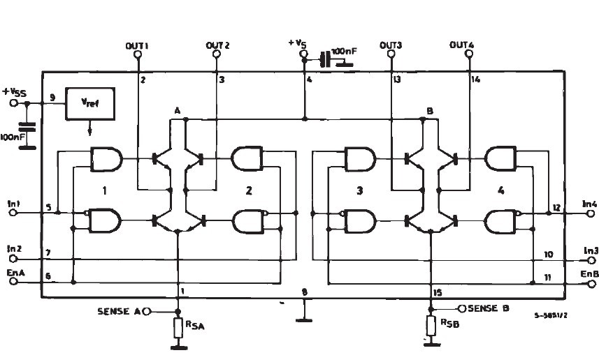 |
|
|
|
Post by Paul Harman on Nov 25, 2014 16:15:41 GMT
Martin
Two L272M should have been adequate (3.2A). It sounds like CV9 might still need tweaking. The L298N should be OK if perhaps a bit big to accommodate being a 16-pin package.
Connect the sense pins and the ground pin to 0V (PIC pin 8), connect VSS and the enable pins to +5v (PIC pin 1), Vs to the blue wire, In1 and In4 can be paralleled (PIC pin 3) as can In2 and In3 (PIC pin 5). Out1 and Out4 will be one side of the motor with Out2 and Out3 on the other side. No need to cut the stripboard between pins 6 and 12, 7 and 10, 6 and 11 to make life easier.
See how you get on.
|
|


 )
)